


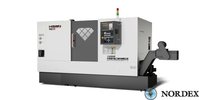
Description
| Name | Units | TC25 || ×500 | TC25 || ×1000 | |
|---|---|---|---|---|
| Opportunities | The largest diameter | mm | Φ560 | Φ560 |
| The largest diameter | mm | Φ320 | Φ320 | |
| Max. processing diameter | mm | Φ400 | Φ400 | |
| Max. processing length | mm | 548(≤ Φ320) | 1000(≤ Φ320) | |
| Cartridge size | inch | 8 | 8 | |
| Diameter of the boring rod | mm | Φ50(OptionalΦ65) | Φ50(OptionalΦ65) | |
| Stroke/speed | X/Z stroke | mm | 210/610 | 210/1050 |
| X/Z travel speed | m/min | 24/30 | 24/30 | |
| The spindle | Type of drive | - | Belt | Belt |
| Max. rotation speed | rpm | 4500 | 4500 | |
| Motor power | kW | 11/15 | 11/15 | |
| Max. spindle torque | Nm | 140/250 | 140/250 | |
| Spindle Flange Type | - | A2-6 | A2-6 | |
| Diameter of the front spindle bearing | mm | Φ100 | Φ100 | |
| Revolver head | Type of revolver head | - | Hydraulic | Hydraulic |
| Number of instrument positions- | 12 | 12 | ||
| The cross-section size of the incisors | mm | 25×25 | 25×25 | |
| Diameter of the axial tool | mm | Φ40 | Φ40 | |
| Tool change time (including clamp) | sec | 0.55 | 0.55 | |
| Grandma | Type of headstock | - | Hydraulic | Hydraulic |
| The course of the grandmother | mm | 410 | 730 | |
| Tailstock pinole diameter | mm | Φ100 | Φ100 | |
| Pinole Move | mm | 120 | 120 | |
| Type of pinole | - | MT NO.4 (Optional Dead MT No.4) | MT NO.4 (Optional Dead MT No.4) | |
| Servo motor | Power of the X/Z servo motor | kW | 1.8/1.8 | 1.8/1.8 |
| X/Z servo motor torque | Nm | 11/11 | 11/11 | |
| Power consumption | kVA | 25 | 25 | |
| COOLANT tank capacity | L | 200 | 250 | |
| The controller | - | FANUC 0I-TF | FANUC 0I-TF | |
| Machine dimensions | Length | mm | 4200 | 4600 |
| Width | mm | 2050 | 2050 | |
| Height | mm | 1900 | 1900 | |
| Weight | T | 4.5 | 4.9 |
Standard configuration [Note: "●" standard, "●" option, "1000000" not included]
| № | Title | TC25 II |
|---|---|---|
| 1 | The controller | FANUC 0i-TF |
| 2 | Hydraulic and lubrication system | ● |
| 3 | Coolant supply system | ● |
| 4 | Closed processing area | ● |
| 5 | Number of instrument positions | 12 |
| 6 | Blind hydraulic chuck | ● |
| 7 | Tool blocks | ● |
| 8 | The headstock with a retractable pinole | ◎ |
| 9 | Hydraulic headstock | ◎ |
| 10 | External chip conveyor (side) | ● |
| 11 | Standard delivery set | ● |
| 12 | Outdoor installation | ● |
| 13 | A set of tools for maintenance | ● |
| 14 | Soft fists | ● |
| 15 | 3-color warning light | ● |
| 16 | Footswitch | ● |
| 17 | The chip cart | ● |
Options for TC series machines [Note: "●" standard, "─" option, "1000000" not used]
| № | Title | TC25 II |
|---|---|---|
| 1 |
Hollow hydraulic chuck
|
◎ |
| 2 |
Red-hot fists
|
◎ |
| 3 |
Programmable tailstock
|
◎ |
| 4 |
Revolver head with a driving tool
|
◎ |
| 5 |
Electric cabinet air conditioning
|
◎ |
| 6 |
Hydraulic lunette
|
◎ |
| 7 |
COOLANT Water Gun
|
◎ |
| 8 |
Air gun
|
◎ |
| 9 |
Automatic door
|
◎ |
| 10 |
A window for managing auth. operations
|
◎ |
| 11 |
Instrument measuring device
|
◎ |
| 12 |
Automatic feeding of the workpiece
|
◎ |
| 13 |
Cartridge blowing
|
◎ |
| 14 |
Coolant supply through the tool (1-7MPa}
|
◎ |
| 15 |
Oil separator
|
◎ |
| 16 |
Oil separator
|
◎ |
| 17 |
Transformer
|
◎ |
| 18 |
External chip conveyor (rear)
|
◎ |
Under order
Similar products


