We present to your attention an algorithm for selecting the most suitable designs of band saws, which draws attention to the properties of the materials to be processed. To calculate the wear resistance of band saws, the total cross-sectional area of the workpieces that have undergone the cutting procedure is taken into account ∑ S, m2.
Also, the cross–sectional area of already cut parts can be taken as the basis for calculating the durability of saws, corresponding to the length of the web - C, m2/L.
When calculating the wear resistance of the web, it is recommended to use the formula:  S is the value of the cross-sectional area of the workpiece m2; N is the number of passes for cutting workpieces; L is the index of the length of the web, m.
The formula is used to calculate the durability when processing solid and thick-walled profiles of standard shapes and sizes.
In cases where thin-walled blanks of small sizes are cut, the value of the total number of blanks that have been processed ∑ n (pcs.) is taken as the basis for the durability indicator.
This is due to certain difficulties in calculating a large number of areas of all blanks with complex shapes.
The wear resistance values of band saws m2/m, having maximum and minimum values for different steels and the use of bimetallic saws are indicated in the diagram (Fig. No. 1).
 The wear resistance values min and max allow us to take into account the machinability of various steels for individual batches of workpieces, the design features of machine tools and the standard sizes of saws.
Thanks to formula 1, it is possible to calculate the overall wear resistance of many groups of processed materials without correlation with the length of the web.
Due to this, it is possible to achieve the application of stability C in the economic planning of the integration of belt cutting technology into industrial production.
The shape of the chips produced can serve as an indicator of the wear of the band saw.
Due to this, it is possible to identify the level of wear of its teeth and adjust the cutting modes.
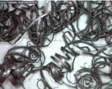
In Figure 2, you can see the chip configuration obtained by processing various types of steel using bimetallic saws with a step of 3/4 tpi.

rice.
2, a.
Drain chips produced during the processing of steel grade 45 and a blank diameter of 160 mm.(the saw used is M42 4450x34x1,1 – 3/4 tpi, v=55 m/min, S=30 mm/min).
There is a silver-colored chip with elongated spirals located along its axis.
This is due to the lack of cutting blades.
The spirals are 8-25 mm long and 3-8 mm in diameter.
The coils of the spring have different compression densities.
This occurs when cutting blanks with round shapes.
All this has an effect on the degree of cut length in terms of cross-section size 0-160 mm.
rice.
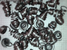
2, b
Drain chips of steel grade 09G2C.The diameter of the workpiece is 110 mm.
(the saw used is M42 4450x34x1,1 – 3/4 tpi, v=55m/min, S=45 mm/min) The length of the observed spiral at the chip is 3-9 mm.
The diameter is 3-8 mm.
rice.
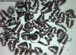
2, in
Drain chips of steel grade 40X.The diameter of the workpiece is 110 mm.
The length of the chip spirals is 3-9 mm, diameter 3-8 mm, (the saw used is M42 4450x34x1,1 – 3/4 tpi, v=50 m/min, S=35 mm/min).
rice.
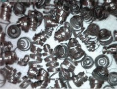
2, g
Drain chips of steel grade 30HGSA.The diameter of the workpiece is 100 mm.
(the saw used is M42 4450x34x1,1 – 3/4 tpi, v=45 m/min, S=30 mm/min).
The length of the chip spirals is 4-10 mm, the diameter is 3-6 mm.
rice.
2, d
Drain chips of steel grade 40KHN2MA.The diameter of the workpiece is 160 mm (the saw used is M42 3330x27x0.9 – 3/4 tpi, v=60m/min, S=23 mm/min).
The length of the chip spirals is 4-14 mm.
The diameter of the spirals is 3-8 mm.
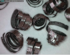
rice.
2nd
Drain chips of steel grade 45KHN.The diameter of the workpiece is 160 mm (the saw used is M51 5900x41x1,3 – 3/4 tpi, v =35 m/min, S=22 mm/min).
The length of the chip spirals is 4-7 mm.
The diameter of the spirals is 7-13 mm.
A characteristic feature for most groups and grades of steels is the formation of chips in the form of elongated spirals.
This shape is formed due to the divorced teeth.
Spiral chips without axial displacement are produced due to the straight teeth of the cutting blade.
At the same time, when using steels of different grades, it is allowed to produce chips with tightly twisted spirals.
This happens with a small volume of the cavity between the teeth of the ribbon web.
In the process of band sawing, the resulting chips can be characterized by parameters such as length, compression density and diameter.
The diameter indicator is influenced by the properties of the material of which the workpiece consists.
The angle of the cutting edge of the teeth, the size of the interdental pitch and the interdental cavity are also important.
The shape and dimensions of the workpiece are taken into account.
The compression density of the turns of the produced chips is influenced by the size of the workpiece and the pitch of the teeth of the ribbon web.
If the interdental cavity is of insufficient size, then the resulting chips change their shape, and its spirals twist.
This is shown in Figure 3.
 There are many forms of drain chips obtained during the processing of BRAZH9–4.
The diameter of the workpiece is 220 mm (the saw used is M42 2740x27x0.9 – 2/3 tpi, v = 40 m/min, S=10 mm/min).
The chip spirals are 4-10 mm long.
The diameter of the spirals is 9-17 mm.
Based on the data obtained experimentally, it was found out that the characteristics of drain chips obtained during the processing of non-ferrous metals and steels of various grades can be absolutely identical.
When using webs with a constant interdental pitch and the same location of the cutting edges, the diameter of the turns of the produced chips is almost always the same.
In the case of band webs having a variable interdental pitch, different sizes of depressions between the teeth and different distances between the cutting edges of the teeth, the diameter of the spiral of the produced chips may be uneven.
The Nordex company, based on many years of experience in integrating sawing technology using band saws, was able to develop a special algorithm that allows for the selection of webs for band sawing, taking into account various production aspects.
The selection algorithm is shown in Figure 4.
 The article highlights the urgency of the need to improve the processing process by gear milling with worm cutters of gears having cylindrical shapes.
The need to increase the productivity of the processing process is indicated.
A solution to the problem of increasing productivity by creating more optimal conditions for the operation of the cutting tool is proposed.
The author proposes a method of gear milling by using the pulse feed method.
The article describes in detail the proposed method.
Its technical features and advantages are shown.
15 Martha 2021